What do all the knobs do on the SSL UC1?
The Basics
As you might expect from a pedigree that dates back decades there is a lot to consider when using the UC-1. To make things simple and for the purposes of brevity I have included links that explain some of the technical terminology that has grown up around the naming of the knobs (highlighted in blue text)
So you have your UC1 setup with your 360 software and you have been toying with the knobs to begin to gain an understanding of what they do. So while the UC-1 is a sexy animal, the processing that it covers probably isn’t – but don’t let that put you off! The focus is on getting what might be considered the “raw” sounds to sound as good as they possibly can. For sure this is the place to start before you think about adding Reverbs and Delays and other effects. There are a couple of sensible places to start to begin to understand the intricacies of the UC-1 and I would encourage you to do both:
- Grab you favourite track in your DAW of choice and play with the pre-sets (13, below) – observing the settings as well as the impact on the sound, mixer track by mixer track
- Read the rest of this blog post and watch the accompanying videos
Perhaps the best key to understanding is to go to the plugins that the UC-1 was built to control. In the first instance there are:
- The Channel Strip 2 Plugin
- The Bus Compressor 2 Plugin
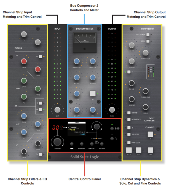
Looking at the image above you can see that the Channel Strip 2 plugin sits at either edge of the UC-1 surface and the Bus compressor 2 in the middle top. At the bottom-centre of the UC-1 there is also the “Central Control Panel” which can be used to navigate the 360 mixer (and your own DAW’s mixer) as well as giving us some other useful functionality such as basic transport controls .

- Track Name Name of the track the Channel Strip is inserted on & the plug-in number order within the 360° Plug-in Mixer window.
- Bypass Toggles Plug-In Bypass In/Out
- 360°Quick Access to open the SSL 360° Plug-in Mixer
- Input Section Input trim control with +/-20dB Gain & Polarity Invert Button
- EQ 4 Band EQ with LF, LMF, HMF & HF bands with Bell options on LF & HF bands, with additional Hi Pass & Low Pass Filters
- Dynamics Dynamics section with Compression & Gate/Expander processing.
- Process Order Window Allows for re-arrangement of processors on the incoming signal or S/C signal.
- Input/Output Meters Large Input & Output Signal meter with summed RMS metering alongside.
- Channel Fader Section Expanded Output section with M/S Width Control & Pan Control (Stereo Only), as well as VCA Modelled Fader Output, Solo, Cut, Solo Clear/Safe, S/C & digital Output Trim
- Plug-In Version Number Shows the current version number of the installed Plug-in
- HQ Enables/Disables ‘High Quality’ Mode, enabling 2x Oversampling.
- Contextual Help Selecting the ? button opens a text window tooltip that will open when the cursor hovers over a controllable parameter. The text box will give a brief explanation of the parameter function.
- Plugin Preset Selection clicking on the preset name will expand a window to enable the selection of SSL presets & user saved presets. clicking this will also allow the current plug-in settings to be saved as a preset for future use.
- A/B Enables the option to alternate between two different settings for comparison without using the preset menu.
- Undo / Redo Enables the option to undo a parameter change, or redo an undone change.
The “Knobs”
It helps to split the knobs into their respective families:
- Filter & EQ
- Dynamics
- Routing and Side-Chaining
The Filter & EQ Family:
Channel Strip 2 features the classic 4-band SSL EQ layout, digitally modelled on the curves of the XL 9000K EQ circuit & includes a 12 dB per octave low pass (LP) filter and 18 dB per octave high pass (HP) filter able to be positioned Pre or Post EQ

| 1. LOW-PASS FILTER 12 dB per octave low-pass filter 2. HIGH-PASS FILTER 3. HIGH FILTER SHELF 4. HIGH/MID FILTER Band 5. LOWER MID FILTER Band 6. LOWER FILTER SHELF 7. E / G Button 8. POWER The EQ can be switched in/out using the EQ button. |
.
The “Dynamics” Family:
The Dynamics section includes a Compressor/Limiter and an Expander/Gate. Both sections work independently but can be operational at the same time, providing sophisticated control of signal levels. The Dynamics section can be switched in/out using the DYNAMICS button.

| 1. COMPRESSOR DRY/WET MIX Determines the parallel mix amount of wet signal added to the Dry pre-compressed signal. 100% means the signal is entirely the signal passed through the compressor section, and 0% is an entirely dry signal path following the previous channel strip processing sections. 50% would be equal amounts wet to dry signal. 2. RATIO 3. THRESHOLD 4. RELEASE 5.FAST ATTACK 6. PEAK / RMS 7. Metering 8. Power |
Bus Compressor 2
Overview

I/O
Bypass

When switched out, the Bus Compressor is bypassed. Where possible, this is linked to the DAW’s insert bypass feature
Compressor
Threshold

Controls the level at which gain reduction is introduced.
Makeup

Provides a gain stage to compensate for any reduction in level caused by compression.
Attack

Controls the response time of the onset of compression once the threshold is crossed. The 20 ms option has been introduced in Bus Compressor 2.
Release
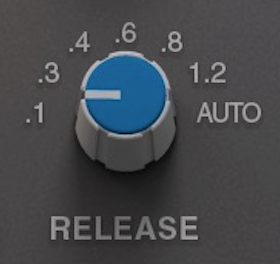
Controls how quickly the level returns to normal. The .4, .8 and 1.2 second options have been introduced in Bus Compressor 2.
Ratio
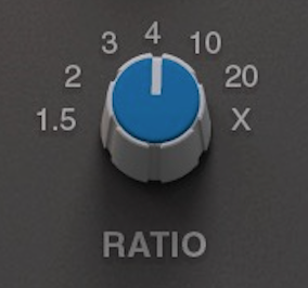
Controls the degree of compression. The 1.5, 3, 10, 20 and X options have been introduced in Bus Compressor 2. X is the most aggressive option – greater than 20, but less than infinity.
S/C HPF
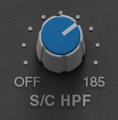
Applies a high-pass filter to the compressor sidechain.
Mix
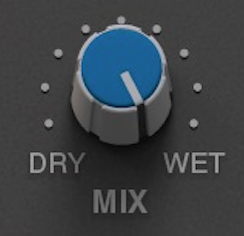
Controls the blend of the processed (wet) and unprocessed (dry) signals. Using a blend between 0 and 100% is commonly referred to as ‘parallel compression’.
Advanced Controls
Oversampling
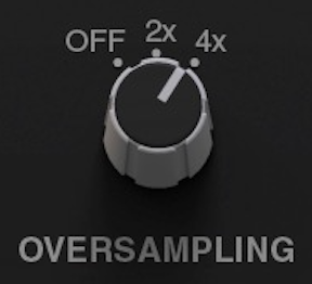
Bus Compressor 2 features the ability to use oversampling DSP. Options are provided for none (OFF), 2x and 4x. When compressing material heavily (e.g. smashing a drum bus), you may want to experiment utilising oversampling, as it will help to reduce unfavourable distortion that may be being introduced. The DAW will introduce a small amount of delay compensation for Bus Compressor 2 when oversampling is used.
External S/C
The EXTERNAL S/C button allows the Bus Compressor sidechain to be fed from a source different to the internal sidechain. e.g. A bus send could be set up in the DAW, such as a kick drum that could be used to creatively ‘pump’ the Bus Compressor. Please note you will need to determine the external sidechain source using your DAW’s plug-in header bar
Mix Lock
MIX LOCK excludes the MIX control from the preset system, which can be useful for auditioning different presets, without the MIX control responding to the preset being loaded.
Metering
Gain Reduction meter
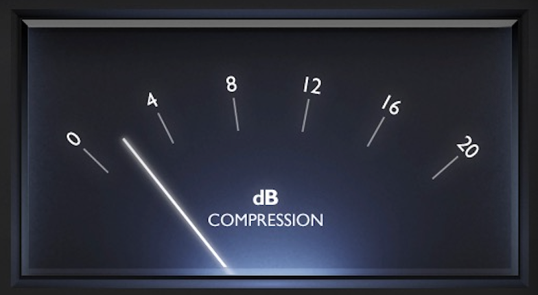
The meter shows how much gain reduction is being applied by the Bus Compressor 2 plug-in in the style of the classic moving-coil meter found on SSL consoles.
